
How to Design and 3D Print a Custom Case for Your Custom Keyboard


Photo: Tim Stevens
Creating a custom keyboard with your choice of switches and keycaps is a great start, but it can be something of a slippery slope. Before long, you're soldering components onto circuit boards and really going wild in pursuit of a boutique cyberdeck or the ultimate ergonomic input device.
Regardless of what keycaps and switches you choose, a flat, printed circuit board (PCB) is never going to make for a great input device. It needs a case, and if ergonomics are important to you, that case needs some tilt to it. Raising the middle of a split keyboard is called tenting, a design that's key for reducing wrist fatigue. But how do you elevate a couple of PCBs? That's where 3D printing comes in.
I've built three custom keyboards now, each with very specialized purposes, but my greatest creation is the 50-key machine you see here. I started with a bare PCB and, when I was through, made myself an ultra-low-profile ergonomic device that is key (pun intended) to my daily typing experience. I'm particularly proud of the case, which features a pair of tenting supports that pop together with magnets. Making it was a great learning experience, and I'm going to show you how I did it.
First step: the basic case
We're going to start with the bare minimum: a simple shell to protect the bottom and sides of your PCBs. If you're using a one-piece keyboard, you can still use these same concepts, but you won't be able to tent it in the middle like you can in a split keyboard with two PCBs.
The keyboard I built started with a design called the Gergo, designed by a Canadian company called g Heavy Industries. Gergo has a split layout with 50 keys intended to be used with ultra-low-profile, low-resistance switches.
Which design you choose isn't important. All you need is a way to get the exact shape of your PCB or PCBs into the modeling tool.
I'm using Autodesk Fusion here for modeling because its parametric feature makes it easy to change your design late in the game without having to start over from scratch. Usually. For this first step, though, we won't be able to take advantage of that feature.
You'll need either a DXF or GBR file to start. These are files that define the exact shape of your PCB. Hopefully, your PCB source can provide them for you. Start by importing that into Fusion and use it to create a sketch. A sketch is simply a way of working with two-dimensional shapes.
In your sketch, select Plane -> Offset to create a second line around the outside of your PCB. This will define the outer wall protecting your keyboard. A 2 mm offset is about right, but you can go thicker or thinner.
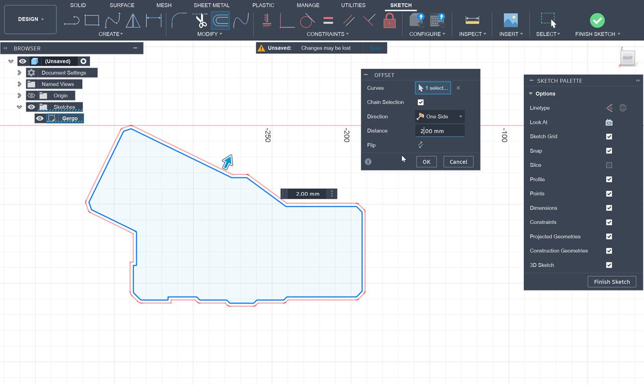
Photo: Tim Stevens
After that, finalize your sketch, and use the Modify -> Press/Pull tool to create the walls. Just click the 2 mm offset line we just created, then enter a height. I used 6 mm, but you can go higher or lower to suit your keyboard. Click "Okay" and boom, your walls are there.
Now, just repeat the same process, but this time select both the offset and the center of the PCB from the sketch you made earlier. Go -2 mm here, select to join with the body you created before, and you have a complete case!
Now, you can add tabs or areas for screws if you want here to hold the PCB, but in my experience, it'll sit tightly inside with no need for that. I had to make a few cuts in the wall to leave room for the cables, but that was it.
If you're working with a split PCB, the final step is to choose Create -> Mirror to duplicate that case, name the two bodies something like "Left Case" and "Right Case," and you're ready to start with the tenting.
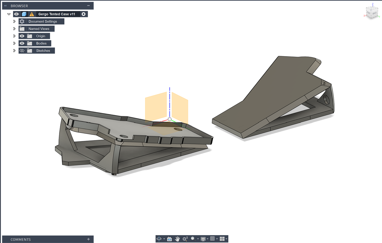
Photo: Tim Stevens
Getting ergonomic
We now have a perfectly functional case, but it's time to get ergonomic. I knew I'd want to go back and forth from tented to flat, so I wanted tents I could pop on and off quickly. Magnets were the ideal solution.
When making your tent supports, you'll want to start with a new project in Fusion. Importing that DXF file earlier disables the parametric timeline. So, copy both the right and left case bodies, make a new project, go to Create -> Feature, and then paste those bodies in.
Once both sides were in, I created a new sketch on the bottom of the cases and used it to position my magnets. I used 5 mm circular magnets, five each per case. So, I drew five 5 mm holes in the corners of the sketch and used those as the template for the Modify -> Press/Pull command to drill through the case bodies, leaving a 0.2mm floor to support the magnets. That means you'll effectively have 0.4 mm of plastic between the magnets, which is plenty enough to ensure they stick together strongly without being difficult to separate.
From there, I used the Create -> Revolve command to project the case at an angle and form the basis of the tented portion. This is a great place for parameterization. If you define a parameter (use the "Change Parameters" command and hit the "+" button) for your desired tenting angle, that'll make it easier for you to retool this model later without having to redo the entire thing every time.
My first tent attempt was at 30 degrees, which is the generally recommended angle for ergonomics. However, the shape of the keyboards I was using didn't seem to work too well at that angle. The centers were too elevated to be comfortable. So, I tried again at 15 degrees, and that was perfect.
Using parameters makes changing angles very quick. And, by separating the keyboard case from the tents, you can even try printing different angles and switch between them until you decide what's most comfortable.
To finish up the tent design, I basically made some cuts in Fusion to hollow out the bottom, used that same magnet sketch to make the reverse holes to place the magnets in the tent supports, and sent it off to the printer!

Photo: Tim Stevens
Printing and assembly
I printed everything off on my home printer. The shape of the tents meant I needed some supports internally to get a clean result, but you may be able to get away without them if you've mastered your printer's overhang settings.
I just used PLA as it's plenty strong enough for this task, but any filament you can print without warping should work just fine.
Once the supports were cleared, assembly just entailed pushing the magnets into the holes. Orientation is key! You want the polarity on all the magnets on the left and right to match, else the case and the tent supports won't hold together. But, do it right, and they'll pop together with a satisfying snap!
To take it a step further, invert the orientation for the magnets on the right case compared to the left. So, if positive is up for the right case and tent, put negative up on the left. That way, you can snap the two tents together, making it much easier to keep them together when you're not using them.
The final touch is adding adhesive rubberized feet to keep the cases and tents from sliding around while you type. Stick a few of these in the corners, and you can be sure your epic, custom keyboard, cases, and tent supports will stay exactly where you want them as you type away in perfect ergonomic harmony.
More from MC News
- Run AI Locally: The Best LLMs for 8GB, 16GB, 32GB Memory and Beyond
- Quantization Explained: Why the Same LLM Gives Better Results on High-End Hardware
- Why Context Length, Not AI Model Size, Is Your Biggest VRAM Problem
- How to Use LM Studio to turn your PC into an AI Server
- Why VRAM and Memory Bandwidth are Key for Powering Local AI
- Keyboard 101: Intro to Computer Keyboards
- Fix It Yourself: Talking to iFixit on Why Repairable Tech Matters
- The Local LLM Your Laptop's Been Waiting For
- Gemma vs Qwen: Which Local AI is Best?
Tim Stevens is a freelance automotive and technology journalist with more than 25 years of experience. Tim frequently contributes to major domestic and international online, print, and broadcast news outlets including MotorTrend, TechCrunch, Wired, CBS and the AP, sharing his insights and perspectives on everything from cybersecurity to supercars.